Description
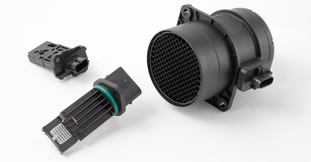
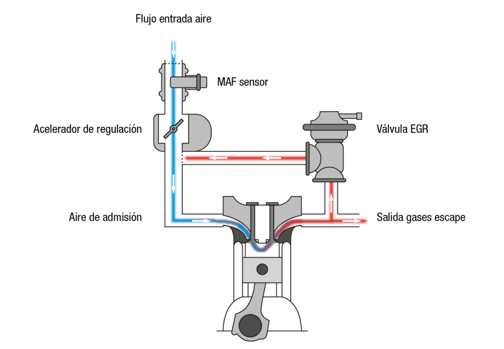
The mass air flow (MAF) sensor, also known as an LMS (Luft Massen Sensor), is located in vehicles before the intake manifold and after the air filter. Its role is to measure the mass of air that the engine is drawing in at each moment and to report it to the control unit via a variable voltage signal.

The MAF sensor plays a fundamental role in reducing environmental impact during the combustion process. The signal it sends to the Engine Control Unit (ECU), along with the signals it receives from other sensors, is necessary for calculating the amount of injected fuel. This helps to ensure efficient engine operation with low emissions.
These sensors operate in conjunction with other key components that optimise exhaust gases, such as EGR valves and oxygen sensors. Their main function is to accurately measure the mass of air entering the intake system in a given period, providing essential information to the ECU.
A dirty or defective MAF sensor can lead to increased fuel consumption and exhaust emissions, as it can no longer accurately determine the optimum amount of fuel required.

Technical data
What are the advantages of FAE’s MAF sensor?
- High accuracy in the measurement of the incoming air mass.
- It responds quickly to changes in air flow, providing real-time data to the ECU to quickly adjust the air/fuel mixture.
- It operates efficiently over a wide range of air flows, from idle to full throttle.
- It incorporates temperature compensation to ensure accurate measurements under various environmental conditions.
- It is compatible with both gasoline and diesel engines.
- It is less sensitive to location and orientation.
- It is durable, as it has no moving parts.
- It eliminates the need for separate pressure and temperature sensors to determine air mass.
- It has a simple, compact and economical design.
What types of MAFs are there?
Currently, there are essentially two types of mass air flow sensors: the hot wire sensor and the hot film sensor.
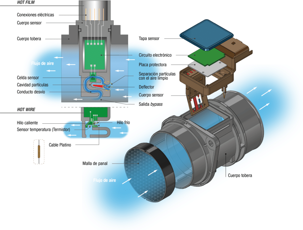
The hot wire sensor has two platinum wires suspended inside the main conduit of the sensor body: a hot wire and a compensation wire, which measures the temperature of the intake air.
The hot film sensor has a thermal resistor, a semiconductor film deposited on a ceramic plate encapsulated in plastic.

These two technologies can be divided according to the sensor’s exposure to the air flow:
- An exposed measurement point
- A bypass conduit
- The bypass conduit design works to:
- Prevent multiple measurements due to pulsation in the intake manifold
- Provide more accurate measurement data
- Avoid inaccuracies caused by backflow or pulsation
- Protect the sensor against contamination
In both cases, since the sensor is exposed to the air flow, particles can be deposited which could alter the sensor’s calibration. To prevent this, the sensor receives additional heating for a few seconds after the engine is turned off to burn off the deposited particles.
Composition
MAF sensors (Mass Air Flow Sensors) are equipped with two temperature sensors that measure the temperature of the intake air and the temperature of the air returning from the engine to the sensor. This function makes it possible to detect and distinguish the return air flow to avoid false readings. Return air is produced when the intake valves are closed, preventing air from entering the combustion chamber.
Depending on the type of thermistor, we can find two variations:
- NTC (negative temperature coefficient)
- PTC (positive temperature coefficient)

Hot wire MAF sensors
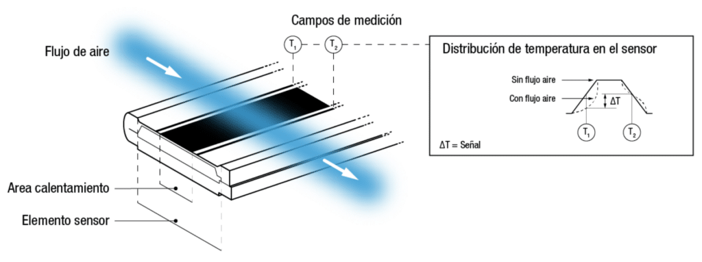
The principle of operation of the MAF sensor is based on the detection of temperature changes that the sensor can sense and transmit to the ECU:
- The thermistor measures the temperature of the incoming air.
- The hot wire is maintained at a constant temperature relative to the thermistor by an electronic control circuit supplying a constant voltage. When this voltage is applied, the filament heats up to approximately 100° C.
- When the air flow increases, the hot wire experiences a loss of heat, which is compensated for by the control circuit increasing the current passing through the wire.
- At the same time, the control circuit measures the current flow, compensates for this decrease and outputs the voltage signal proportionally. Changes in voltage and current are processed by the sensor’s integrated circuit, which sends this voltage variation to the ECU to interpret these changes and make adjustments to fuel delivery.
Hot film MAF sensors
The name refers to its construction. Unlike hot wire MAF sensors, semiconductor film MAF sensors are composed of a thin layer of semiconductor deposited on a ceramic plate, which is then encapsulated in plastic. This design dispenses with the platinum wires present in other MAF sensors. This semiconductor film has 3 resistors:
- The first detects the intake air
- The second detects the air returning from the engine to the sensor
- The third is a heating resistor that is activated by the control unit
This third resistor can reach approximately 150 °C. Due to the flow of both intake and return air from the engine to the sensor, the resistors experience changes in voltage and current. The sensor’s integrated circuit processes this information and sends the voltage variation to the ECU to adjust fuel delivery.
Cause of failure
What can cause a malfunction or breakdown?
- Oil and dirt contamination can impair the accuracy of the sensor.
- Hot wire MAF sensors depend on a stable supply voltage, so any voltage irregularities can affect their accuracy.
- Hot wire MAF sensors depend on a stable supply voltage, so any voltage irregularities can affect their accuracy.
- Excessive oil mist from the crankcase ventilation can dirty the sensor.
- Errors during after-sales maintenance, such as working in an unclean environment when changing the air filter or using an incorrect or lower quality air filter, can damage the mass air flow sensor.
- Water, especially in climates with heavy rain, can penetrate through the air filter and damage or dirty the sensor.
- Saltwater, such as that from de-icing salt and partially melted snow, can exacerbate this effect.
- Oil particles from oiled sports air filters can damage or dirty the sensor.
- Leaks in the intake channel can allow dirt particles to penetrate with the intake air at excessive velocity and damage the sensing element.
Additional problems may influence the accurate reading of the mass air flow sensor and generate an erroneous signal to the ECU.
- Problems with exhaust gas recirculation valves.
- Malfunctioning of the tank air vent valves.
- Leaks in the engine intake channel.
- Obstruction or dirt in the air filters.
- Damage to the turbocharger, such as a poorly calibrated or damaged wastegate valve.
Regular maintenance may be required to clean or replace the MAF sensor if it becomes contaminated in any of these cases.
What are the signs of a malfunction?
Signs that may indicate failures in dirty or faulty mass air flow sensors include:
- Irregular start-up: Initial combustion is incomplete.
- Oscillation at idle: Variations in idle speed, such as high speed, low speed or instability.
- Driving problems: Variations during acceleration, premature ignition (backfiring) of the engine, abnormal detonation or emission of black smoke.
- Engine stall: It occurs immediately after starting, when the accelerator is depressed or released.
- Emission of black smoke.
- Deficient power.
- Emergency mode.
Erroneous readings from a faulty mass air flow sensor can cause the engine control unit to incorrectly activate other components. Therefore, consecutive error messages may be an indication of a defective mass air flow sensor.
False failures or sporadic failures of the mass air flow sensor
Even when the OBD (On Board Diagnostics) shows a sporadic failure of the MAF sensor, it does not always necessarily indicate a true malfunction. Often, moisture, dirt or oil mist can distort the measurement results and cause the OBD to interpret this as a malfunction. Therefore, before replacing it, it is important to perform an initial check. Reasons for this type of sporadic failure may include:
- The warning light only activates if the same malfunction occurs again during the following driving cycles or within a specific period of time. This type of malfunction is known as “anti-rebound protection” (confirmed) and is recorded as a malfunction in the OBD.
- The warning light may also go out if the malfunction does not recur for a specified period of time.
Mounting
Disassembly and installation of the FAE sensor
To disassemble the sensor, follow the instructions below:
- Turn off the vehicle and disconnect the negative (-) battery terminal cable before proceeding with the replacement. Wait at least 90 seconds after disconnecting the cable to avoid any unintentional activation.
- Disconnect the MAF sensor connector. Remove the screws holding the MAF sensor. If the sensor is connected to an air intake conduit, loosen the clamps holding the tube and remove it.
- IMPORTANT: Before installation, check the mounting direction. If the sensor is mounted in the wrong direction, it will not operate.
- Install the new MAF sensor, making sure to secure it correctly with the screws in the air intake conduit. Connect the MAF sensor connector. If the MAF sensor has a suction tube, be sure to tighten all clamps.
- After replacing the sensor, reconnect the negative (-) battery cable.
- Start the engine and verify that the intake system is working properly.
- Check the entire air intake system for possible leaks. Be sure to inspect the O-ring to verify that it is not cracked and that it is properly installed.


