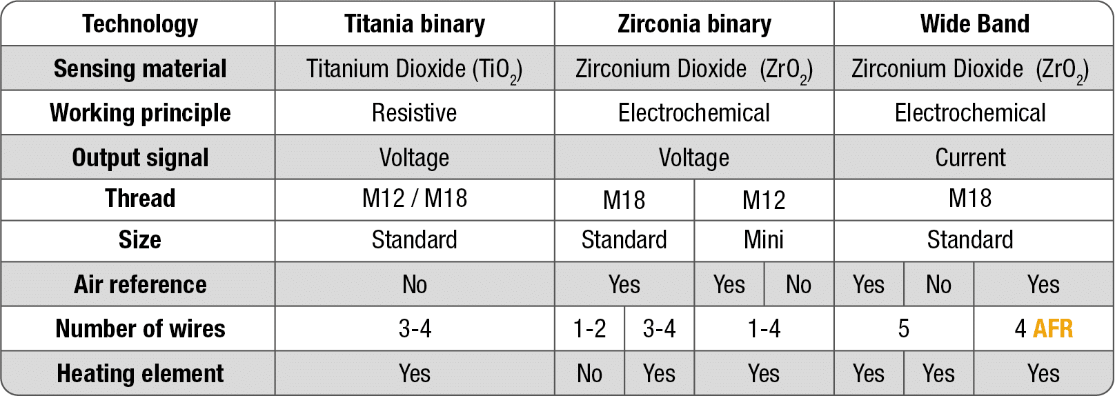
FAE manufactures three types of Oxygen Sensors for combustion control: Binary titanium Oxygen Sensors, Binary zirconia Oxygen Sensors, and Wide Band Sensors. These three types of Oxygen Sensors are not interchangeable with each other as they work differently.
Planar Oxygen Sensors
These Oxygen Sensorsare based on the most modern technology, the ceramic multilayer technology, which distinguishes them from the conventional ones. Thanks to FAE’s Planar Multilayer Ceramic technology, it has been possible to integrate both the sensor element and its heater into a single solid and reduce its size compared to conventional Oxygen Sensors. These improvements do not allow to reduce the heating power and the time needed to reach the operating temperature (700 ºC).
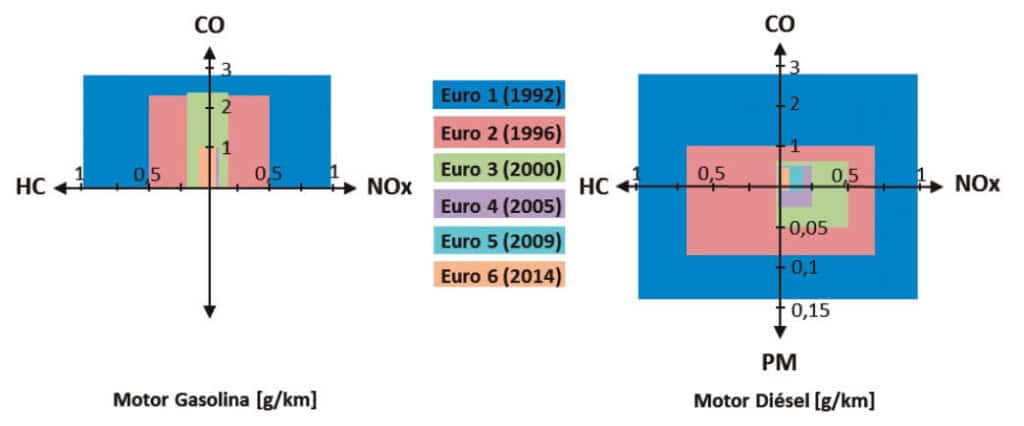
Both the application of increasingly restrictive emissions legislation, and new engine management strategies, lean mix engines, direct injection, etc., have highlighted some of the limitations of conventional Oxygen Sensors. To achieve lower emission limits, “ultra-fast” response Oxygen Sensors are initially needed to avoid pollution at the moment of engine start-up. These improvements have been achieved with the application of Planar Multilayer Ceramic technology that FAE applies for the manufacture of its Planar Oxygen Sensors.
The ignition time or “Light-off” is the time needed by the Oxygen Sensor to warm up and being able to inform the ECU (Electronic Control Unit) about the exhaust gas composition. Using a good condition Oxygen Sensor will ensure:
- Lower emissions
- Improving engine efficiency and performance
- Lower fuel consumption (a malfunctioning Oxygen Sensor can increase the consumption by 15 %)
- Not damaging the catalytic converter
Check the correct Oxygen Sensor performance at least every 30,000 km (20,000 miles).
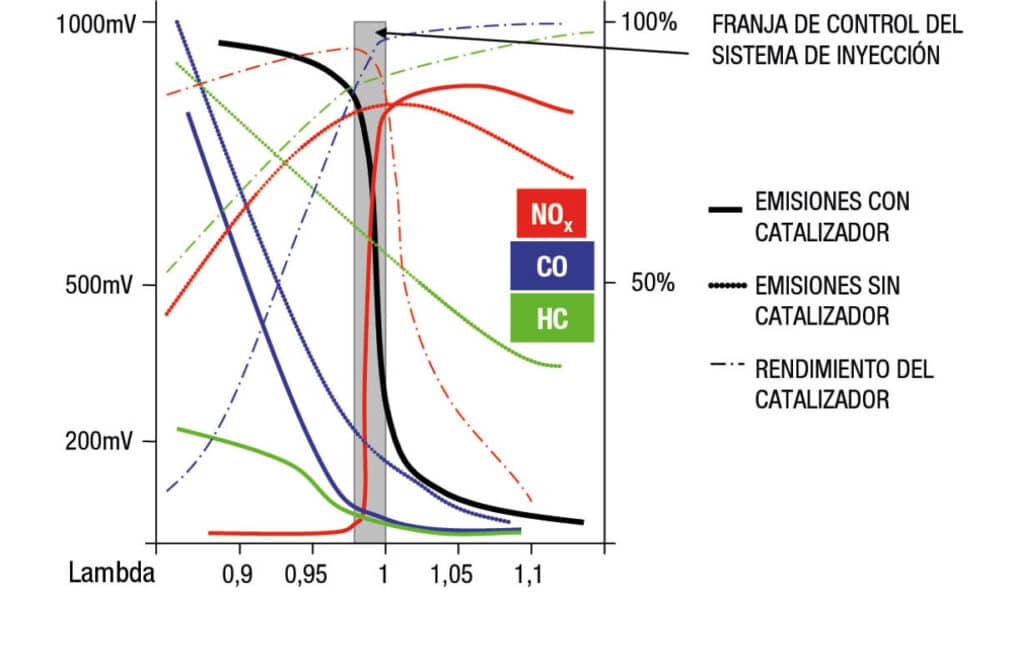
Through the Oxygen Sensor signal, the control unit recognizes the mixture composition. The Oxygen Sensor controls the mixture of the fuel-air ratio and ensures that the engine works at the optimum mixture, Lambda 1. In rich mixtures or ones with fuel excess, Lambda <1, the fuel injection decreases, whereas with oxygen excess or lean mixtures, Lambda >1, the injected fuel quantity is increased till the optimum.
All vehicles with catalytic converter have at least one Oxygen Sensor; the regulation Oxygen Sensor whose function has been already described. This Oxygen Sensor is placed before the catalytic converter. Nevertheless, vehicles applying the OBD-II (on-board diagnostic), the second version of the diagnosis standard, equip a second Oxygen Sensor, a diagnosis sensor, located in the near part of the catalytic converter. Its function is to report the smooth operation of the regulation sensor and the catalytic converter, and to warn when these elements shall be replaced.
Operation and types of Oxygen Sensor
There are different types of Oxygen Sensors. They can be classified attending to their sensing material and their working principle: Zirconia binary Oxygen Sensors (Zr), Titania binary Oxygen Sensors (Ti) and Wide Band Oxygen Sensors.
How binary Oxygen Sensors with ZIRCONIA sensor element work:
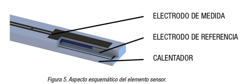
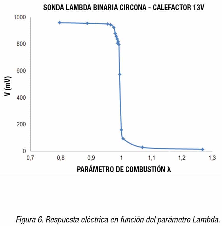
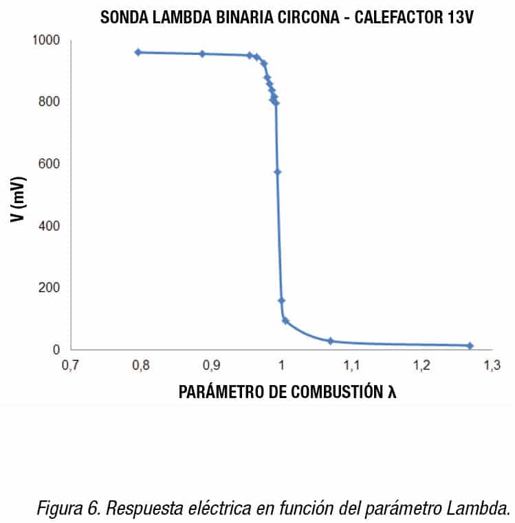
Binary Oxygen Sensors made of Zirconium Dioxide (figures 3, 4) contain a solid electrolyte generating an electric voltage. This output voltage is provided due to a comparison between two atmospheres (exhaust gas in one side and air reference in the other side) and is sensitive to the oxygen concentration in exhaust gases. Rich mixtures lead to a high voltage and low mixtures cause a low voltage, thus giving a kind of on-off response or 0-1. This is easy to detect by the ECU. The sensing material is electrically activated above 350 ºC (662 ºF). Different evolutions can be distinguished among the binary Zirconia Oxygen Sensors:
Unheated Oxygen Sensors: These were the first ones to fit vehicles. They reach the working temperature > 350 ºC (> 662 ºF) when they are exposed to exhaust gases at high temperatures. For this reason, they are located close to the engine. The ignition time or Light-off is higher than 2 minutes. They can use one or two wires. Depending on the application, the sensor housing may be ground-insulated. The lifetime is about 50,000 to 80,000 km (30,000 to 50,000 miles).
Heated Oxygen Sensors: They carry an integrated heating element, reducing its size and reaching the working temperature in approximately 10 seconds. They manage to reduce emissions on the most critical phase; the engine cold-start. They can work with three or four wires (two wires for the heater, plus one or two wires for the output response, with the housing occasionally ground-insulated). Their lifetime is about 160,000 km (100,000 miles). FAE Oxygen Sensors have a heating element integrated in the sensor component, reducing its size and reaching working temperatures in about 10 seconds. They manage to halve emissions from the critical cold start phase. Their lifetime is about 160,000 km (100,000 miles).
How does the Oxygen Sensor with the TITANIA ceramic body work?
This Oxygen Sensor is basically made up of a Titanium Dioxide ceramic body (figure 7). Unlike the Oxygen Sensors made of Zirconium Dioxide (figure 8), its working principle is not electrochemical but resistive. For this reason, the whole sensing material is immersed in the exhaust gas. There is no need of exposure to an air reference for providing a comparison-based signal (figure 9). Titania Oxygen Sensors always include a heater. At high temperatures, resistance of this material is sensitive in front of variations of oxygen concentration. The resistance is minimal for rich mixtures and high for lean mixtures. The sensor is fed with a constant voltage and its output response is read by the ECU by means of a voltage divider.

How do WIDE BAND Oxygen Sensors work?
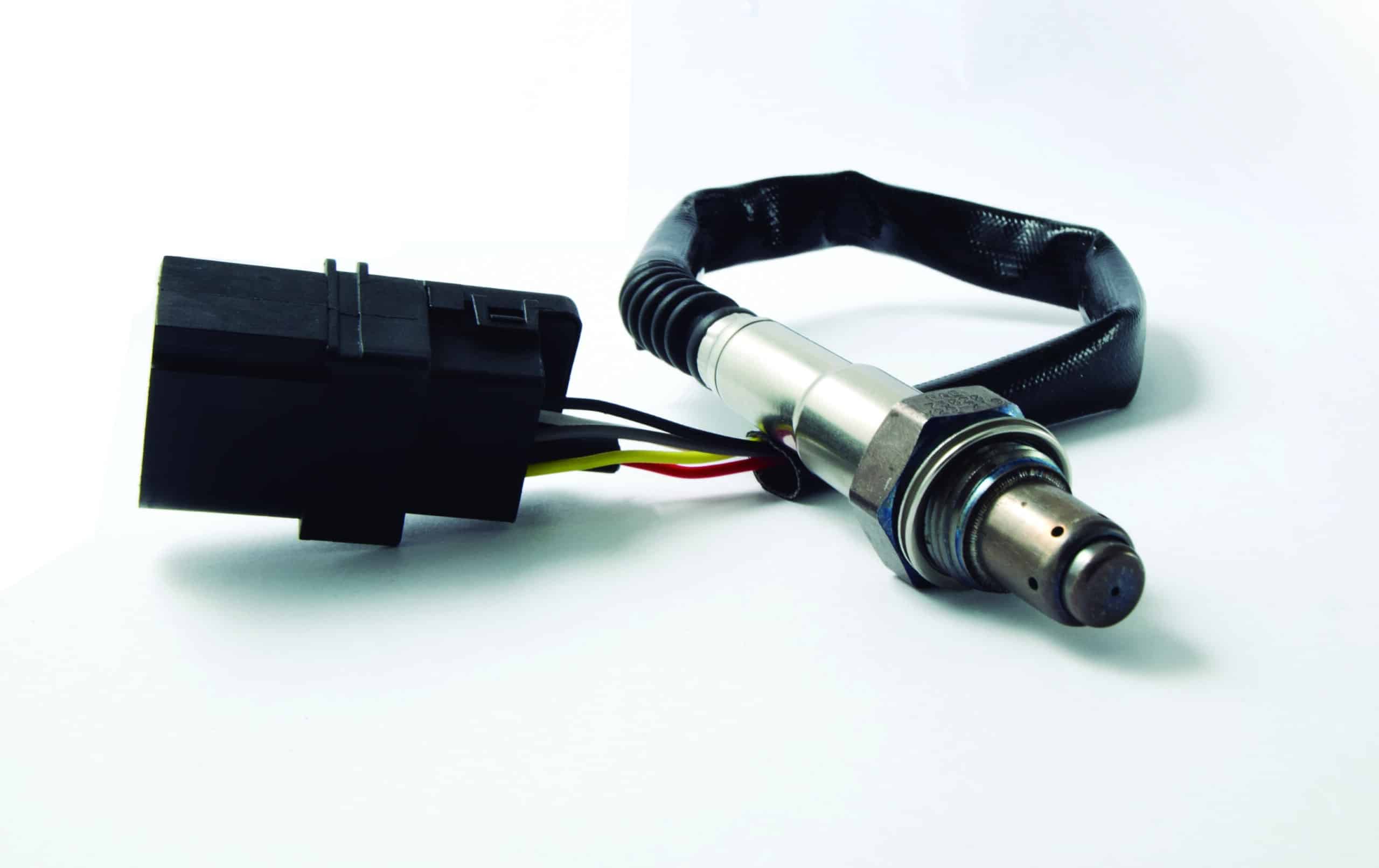
Unlike Zirconia-based Oxygen Sensors, Wide Band Oxygen Sensors provide a continuous response, not binary, in front of the detected Lambda value. Therefore, they measure the exhaust gas composition with good precision. This makes them valid for diesel and gasoline combustion engines.
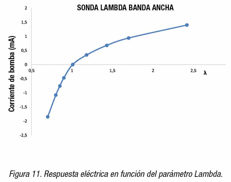
Wide Band Sensors contain two electrochemical cells working concurrently. Of the cells measures the rich or lean character of the exhaust gas mixture, in a similar way as binary Oxygen Sensors work. The other one reacts and is conditioned by the signal of the first cell and the oxygen concentration in the exhaust gas. The whole operation of both cells provides an electric current which is positive for lean mixtures, negative for rich mixtures and null for the case of the stoichiometric mixture.
In opposition to binary Oxygen Sensors, the pumped current of each Wide Band Oxygen Sensor is different. Besides, it is necessary to scale or calibrate this current.
There are three different strategies to calibrate the current of these devices:
Wide Band Sensors with a calibration resistor in the connector. In terms of the total pumped current of each sensor, a resistance is included between two of the output terminals. This resistance is adjusted for each Sensor and its value modulates the net current read by the ECU. When assembling and connecting the sensor in the vehicle, an electric circuit containing two parallel resistors is closed. One of them is the calibration resistor from the sensor, whereas the other one is always the same. The calibration resistor value ranges between 30 and 300 Ω.
Wide Band Sensors with an identification resistor. In this case, resistances cannot take any continuous value, only some discrete values according to 23 different allowed ranges of pumped current. When assembling and connecting the sensor to the vehicle, this resistance which is included in the connector does not close any circuit neither modulates the pumped current, so it is just used as a label to be read by the ECU. When identifying the resistor value, the ECU knows which scale to be taken to detect the sensor pumped currents. The identification resistor value can take several possible orders of magnitude, ranging from hundreds of ohms to tens of kΩ.
Wide Band Sensors with no resistor. During the first seconds of operation, the ECU is able to calibrate the current by means of electronic procedures. Whatever the current calibration strategy is (calibration resistances or identification resistances), the function of the resistor is making possible the detection of the pumped current. Therefore, in general, two sensors of the same reference do not necessarily include the same resistance.
TYPES OF WIDE BAND OXYGEN SENSORS
Apart from the resistance in the connector of the sensors, it is also possible to classify them according to the existence or not of air reference duct:
- First generation Wide Band Sensors, containing an embedded air reference duct, similar to the one in the binary Zirconium-based Oxygen Sensors.
- Second generation Wide Band Sensors, which do not need that reference duct for working. In comparison to the first generation, the lack of inner duct leads to savings in power consumption. Also, the light off time is lower and signal stability through the sensor life time is larger. Second generation Oxygen Sensors may or may not include calibration or identification resistors in the connector.
Depending on each vehicle application, a first or second generation Wide Band Oxygen Sensor is needed. It is not possible to replace first and second generation sensors between them. Their lifetime is about 160,000 km (100,000 miles).
LAMBDA AIR FUEL RATIO A/F SENSORS
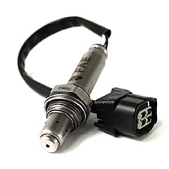 These are 4-wire Wide Band sensors, which provide a proportional signal (figure 11) against the detected lambda value, but with a single electrochemical cell. This cell is regulated by the vehicle electronics and reacts conditioned by the amount of oxygen present in the combustion gas simultaneously. The combined operation provides a characteristic current corresponding to the different gas compositions in the exhaust pipe without the need for prior individual calibration. The current generated is positive for lean mixtures where it is able to measure the gas composition with high accuracy and, in turn, due to its non-limiting reference channel, is sensitive to rich, oxygen-free mixtures by being able to generate current in the opposite direction; this makes it suitable not only for diesel engines, but for petrol engines too.
This sensor is equivalent in response to a 5-wire Wide Band, because the signal it gives is proportional to the lambda, which leads to more efficient emission control, but unlike the 5-wire, this sensor requires only one electrode cell.
Remember that the signal trim is a resistor that adjusts the current signal given by the sensor in the wide band so that variations in output are corrected and all sensors manufactured give the same signal. It has only one electrochemical cell, which means less use of platinum and, in turn, a very bulky reference channel so as not to be a limiting factor in rich mixture signals. For example, for a diesel, this would not be necessary, as rich lambdas cannot be read with this type of fuel. The materials used are an incredibly important element, which is why at FAE we design and manufacture our own materials, and in the manufacture of this new sensor we’ve needed to incorporate new materials, which is why it’s essential to replicate the same materials batch after batch without any variation in their characteristics.
After fine-tuning the sensor to a robust and reliable design, we put the sensors through a number of extremely demanding tests, such as thermal shock with drastic temperature changes, heater fatigue with continuous on/off switching, and life testing with extreme operating conditions. Functional testing, current and signal testing, electrical isolation testing, signal stability testing, etc. We carry out a characterisation of thermal resistance, with and without water condensation, life tests of the different components of the sensor, replicating the operation of the sensor in a car, as well as contamination tests, either by a chemical agent or by being in a saline environment, watertightness tests, etc.
Afterwards, and once the sensor is mounted with a complete probe, we carry out life tests on an engine bench, where the sensors are working for thousands of hours, as well as on real vehicles that accumulate thousands of kilometres. The lab tests are over 2,000 hours. The mileage in real applications is more over 200,000 km in different vehicles to ensure the compatibility of the sensor across vehicle applications, to offer the market a highly resistant and 100% reliable product.
Causes of Oxygen Sensors failures
Verify that the connector and the cable are visually in good condition. Also verify if the body of the Oxygen Sensor shows any dents or signs of being hit that could have caused damage.
It is necessary to consider, as a normal guideline, that a visual inspection is not enough to be certain that the Oxygen Sensor is working properly. Besides the recommendations made above, we should also pay attention to the condition of the protection tube to have an indication of the possible problem.
- Oxygen Sensor damaged by excess lead in the emission gases
- Oxygen Sensor damaged by coolant leaks
- Oxygen Sensor damaged due to an air / fuel mixture that is excessively rich
- Oxygen Sensor damaged by high engine oil usage
- Oxygen Sensor damaged due to contamination from silicon in the emissions gases
Remember that anytime you encounter one of these situations you should replace the Oxygen Sensor.
1 2
2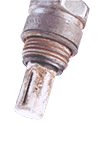 3
3 4
4 5
5
Installation of an FAE Oxygen Sensor
FAE Oxygen Sensors are installed quick and easy. Remember that the engine must be cold, if not you must take the necessary precautions since the Oxygen Sensor reaches very high temperatures and you might run the risk of burns. The installation requires to soak the thread with a special grease. This grease will facilitate the disassembly and will prevent the Oxygen Sensor from remaining welded to the exhaust pipe due to the extreme working conditions. FAE Oxygen Sensors are delivered with a greased thread. Nevertheless it would be convenient to double check.
The Oxygen Sensor tightening is another important aspect. Apply below indicated torque and be aware that tightening too strongly can deform the thread:
- Oxygen Sensors with a M18 thread, tighten to 35-45 Nm (25-33 ft lb).
- Oxygen Sensors with a M12 thread, tighten to 18-23 Nm (13-7 ft lb).
How is a Universal Oxygen Sensor installed?
It is recommended that after a major collision they check the Oxygen Sensors or replace them. To install the Universal FAE Oxygen Sensor you must follow the following steps:
- Before installing the Oxygen Sensor, make sure to use the appropriate reference for your vehicle.
- Don’t install the Oxygen Sensor if it has been hit or seems to be damaged.
- Disconnect the battery. Disconnect the old Oxygen Sensor lead wire connector. Remove the old Oxygen Sensor from the vehicle.
- Cut the lead wire(s) approximately 15cm (6 inches) on the old Oxygen Sensor separating the connector from the rest of the sensor
- Strip the insulation (according to the indicated length) from the old lead wire(s) with the attached connector, making sure that no damage is done to the inner wire.
- Insert the stripped wire leads into the caps of the new FAE Oxygen Sensor. Be aware of matching the colours of the wires.
- Crush the caps. Heat the heat shrink tube until it forms a tight, fixed seal between the old connector and the new Oxygen Sensor.
- Once the process described above is complete, you are ready to install the new FAE Oxygen Sensor.
How is a Specific Oxygen Sensor installed?
It is recommended that after a major collision, check the Oxygen Sensors or replace them. To install the FAE Universal Oxygen Sensor, you must follow the next steps:
- Before installing the Oxygen Sensor, make sure to use the appropriate reference for your vehicle.
- Don’t install the Oxygen Sensor if it has been hit or seems to be damaged.
- Disconnect the battery
- Remove the old Oxygen Sensor from the vehicle
- Place the Oxygen Sensor in its location and check it the wires are not twisted, doubled or trapped.
- The Oxygen Sensor tightening is another important aspect. Apply below indicated torque and be aware that tightening too strongly can deform the thread:
- Oxygen Sensors with a M18 thread, tighten to 35-45 Nm (25-33 ft lb)
- Oxygen Sensors with a M12 thread, tighten to 18-23 Nm (13-7 ft lb)
- Install the new Oxygen Sensor lead wire(s) exactly as they were originally installed in the old replaced Oxygen Sensor, taking special care in keeping the wires away from the exhaust manifold (or from any other hot element), or from any moving parts.
How are the Oxygen Sensors tested?
To verify the proper working of the Oxygen Sensor, without removing it from the vehicle, use an oscilloscope. To obtain a proper reading the basic engine set up according to the manufacturer’s specification has to be full filled and ensure that the engine is thoroughly warmed. Connect the Oxygen Sensor output to the oscilloscope, without disconnecting the Oxygen Sensor from the vehicle’s ECU. Once the connections are made, keep the engine running at 2,000 rpm. Under these conditions, if the Oxygen Sensor is working properly, the signal from the oscilloscope will fluctuate rapidly and constantly between 0.2 volts (lean mixture) and 0.8 volts (rich mixture).
Another important fact to keep in mind is the time needed for the voltage to change. It should be about 300 milliseconds. The time to switch from a lean to a rich mixture and from a rich to a lean mixture should be the same or very close. By the signal generated the Oxygen Sensor is constant and the reaction time to change the mixture is too slow, the Oxygen Sensor has to be replaced. It is recommended to test the performance of the Oxygen Sensor each maintenance and always before an emissions test. A malfunctioning Oxygen Sensor has an adverse effect on your fuel economy. When replaced as required, a new Oxygen Sensor will contribute to lower vehicle operating costs and the investment in replacing it will be rapidly paid back.
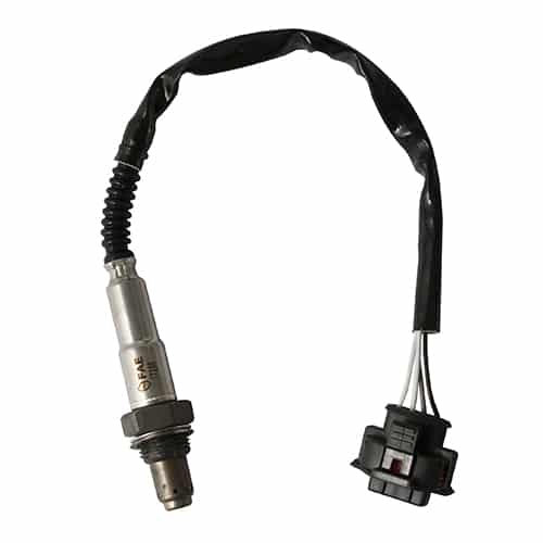


 These are 4-wire Wide Band sensors, which provide a proportional signal (figure 11) against the detected lambda value, but with a single electrochemical cell. This cell is regulated by the vehicle electronics and reacts conditioned by the amount of oxygen present in the combustion gas simultaneously. The combined operation provides a characteristic current corresponding to the different gas compositions in the exhaust pipe without the need for prior individual calibration. The current generated is positive for lean mixtures where it is able to measure the gas composition with high accuracy and, in turn, due to its non-limiting reference channel, is sensitive to rich, oxygen-free mixtures by being able to generate current in the opposite direction; this makes it suitable not only for diesel engines, but for petrol engines too.
 2
2 3
3 4
4 5
5