In this report we will talk about the Oxygen Sensors we manufacture at FAE and the evolution of this product over the years.
1. INTRODUCTION TO THE LAMDA SENSOR
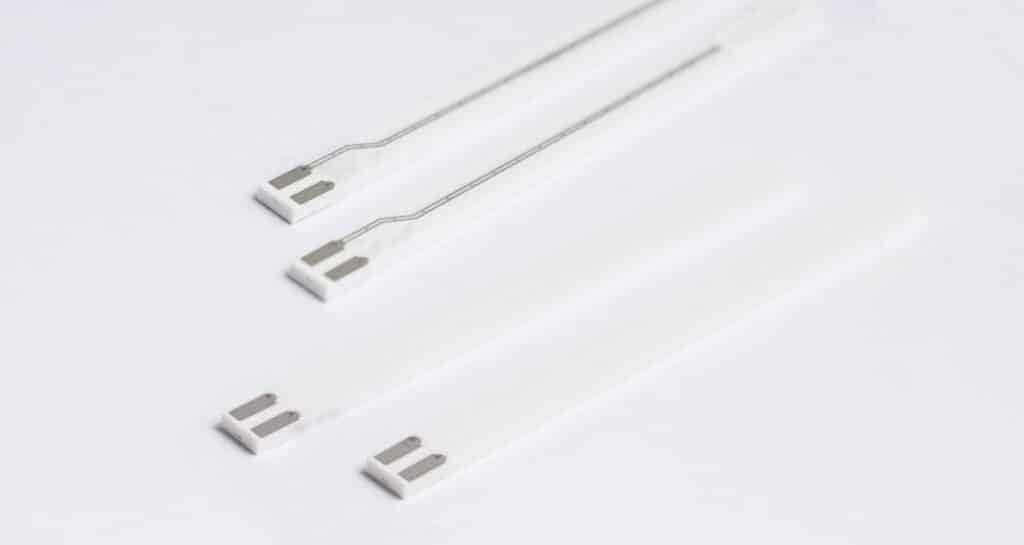
FAE uses multilayer planar technology to manufacture its Oxigen sensor sensors. The sensor is made up of different layers of a ceramic substrate. Each of these layers has a different function; each layer is configured separately, and they are then joined together one by one to form a set with complete functionality.
1.2. STRUCTURE OF THE LAMBDA SENSOR
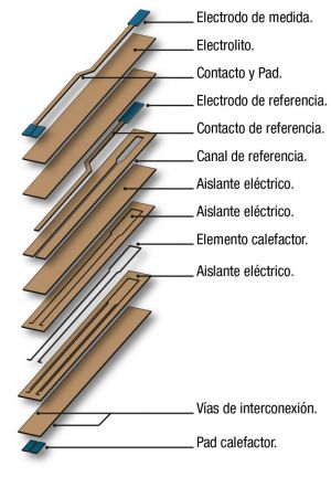
FAE Lambda sensors work by comparing two atmospheres: exhaust gas and external air. The difference in the oxygen concentration of the two gases generates a voltage in the sensor which is read by the car’s Electronic Control Unit (ECU). In order to do this, within the same sensor there have to be different parts in contact with the exhaust gas (measuring electrode) and with the clean external air (reference electrode). The sensor also needs a resistant Heater, as well as connective paths and insulating parts to avoid interference.
Each and every one of these parts is located in a layer customised for its function. These layers will be stacked and compacted to form a sensor.
2. FORMULA AND MIXING
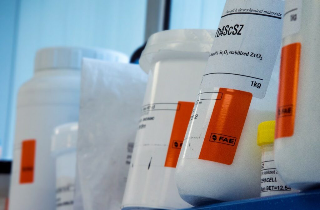
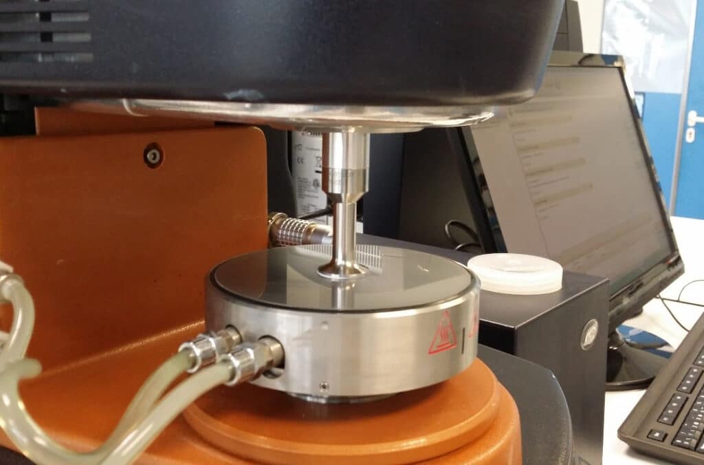
The base material with which FAE sensors are manufactured is a ceramic material called barbotina. To create it, we start with an initial material that is a Zirconium Dioxide ceramic powder that, mixed with a water base and various additives, becomes a paste with plastic properties, similar to aqueous paints. The mixture is made using a monitored manufacturing protocol. The homogenisation is carried out using mixers and mechanical filtering systems, which guarantee the viscosity and homogeneity of the product, and is controlled by a rheometer.
3. CAST
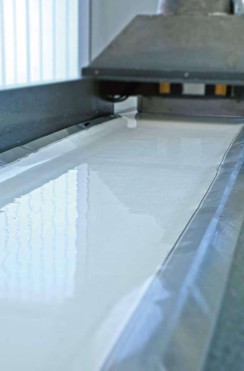
The ceramic substrate is created in this machine, which forms a continuous tape with a thickness of 200 microns. The ceramic paste is deposited into a transporter material of siliconised PET (Polyethylene Terephthalate), which advances at the speed of 1 linear metre per minute through a system of valves, which ensure that the ceramic is deposited homogeneously. Immediately afterwards, the barbotine cast is dried at a controlled temperature and develops a flexible consistency similar to paper. This material has flexible, plastic properties which come from the organic additives. In this state, the ceramic is known as “ceramic in green”.

The coil obtained in the casting machine FAE is sent for processing to the Clean Room which, thanks to the control of its atmosphere, is essential for manufacturing with multilayer planar technology, to ensure that there are no dust particles between the ceramic layers, which compromise the quality and functionality of the product FAE.
4. CUTTING INTO SHEETS
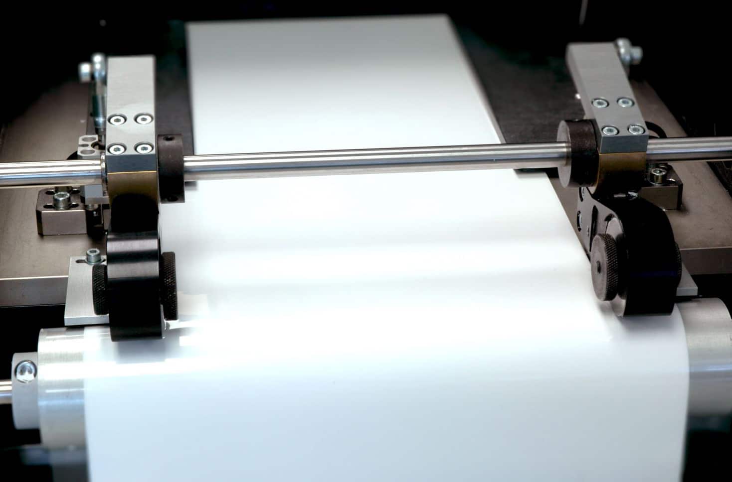
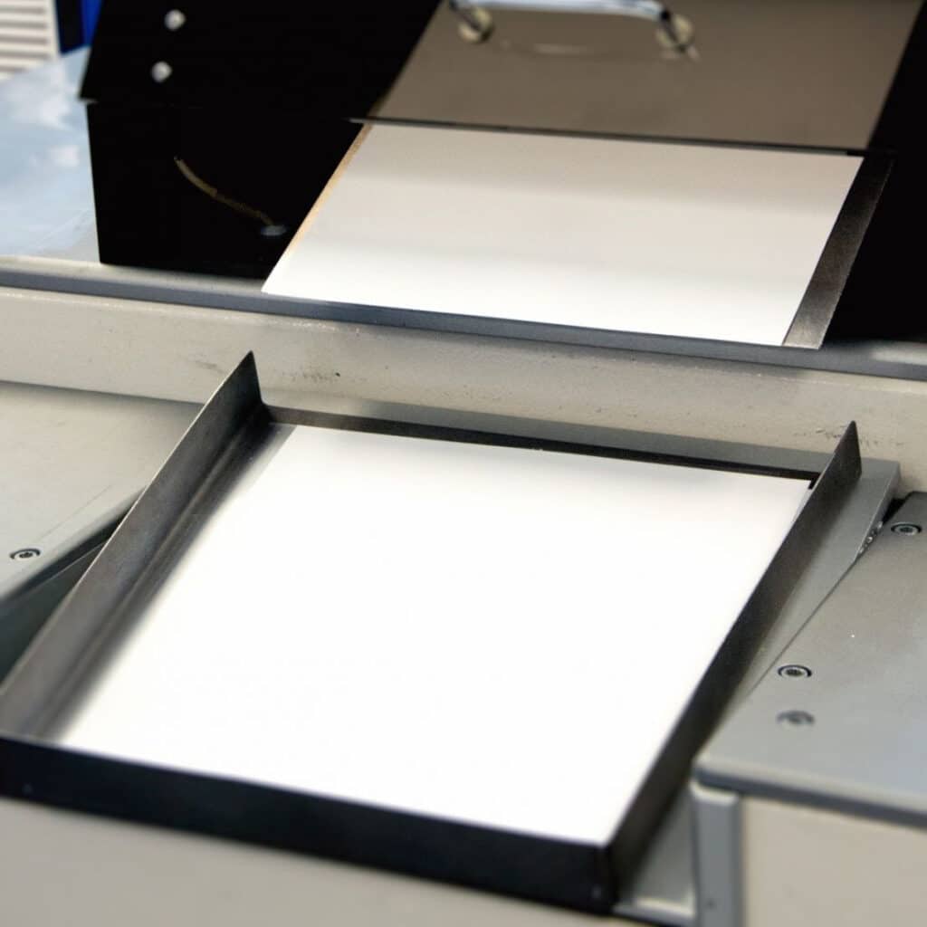
The ceramic substrate roll enters the machine and is cut very precisely into sheets of the appropriate size needed for its automatic processing by all the relevant equipment. Each roll of ceramic substrate makes the number of sheets necessary for manufacturing about 3000 sensors.
Once each sheet has been cut, it is then weighed, and its thickness and homogeneity are controlled by artificial vision cameras. These can detect any pore, crack or irregularity in the substrate. Holes or fiducial markers are made on the sheets in order to facilitate the control of their position by artificial vision cameras.
5. HOLE PUNCHING
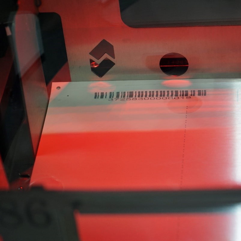
This machine customises each sheet for the function it will need to perform in the sensor. Depending on the type of sensor being made, some layers will be used to house the heater, while others will be used for electrolytes, insulators, etc. For this reason, it’s necessary to make different types of holes or cuts in the sheets. These holes have a maximum size of 300 microns. These holes or cuts will later be filled with special conductive inks. The fiducial markers assure that the holes made in each of the tapes will coincide perfectly when they are layered on top of each other to form the layers of each sensor.
6. INKS
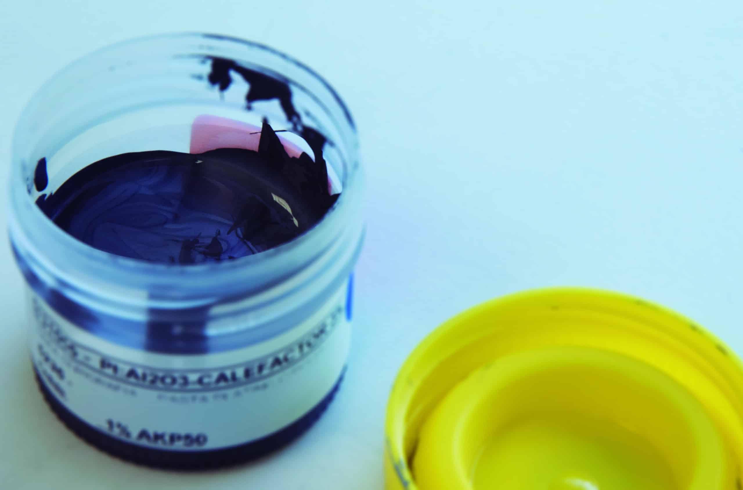
In the preparation of inks FAE is one of the secrets of manufacturing this type of sensor for lambda probes, since these inks have a specific formulation for each function and contain metals such as platinum that provide the lambda probe sensor with the required functionality.
7. FILLING TRACKS
This machine fills in the previously made cuts or tracks with the conductive inks that have been specially created for each function.
8. SCREEN PRINTING
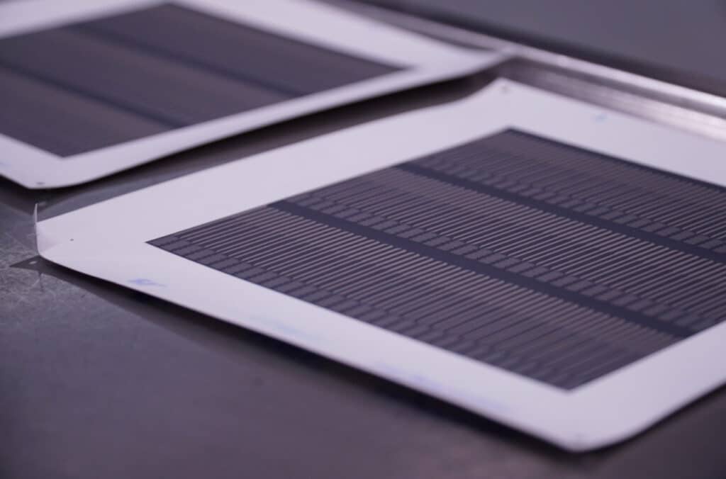
Screen printing is used to create the FAE electronic circuits. This is similar to the printing used on t-shirts, but done with extreme precision.
Through the control of the artificial vision camera, the punched tape is perfectly lined up with the printing plate in order to pass the ink. Then, it’s weighed, and the thickness is checked. Depending on the required thickness of the ink, up to 3 passes may be necessary.
Afterwards, the inks are dried in an oven.

9. PROFILOMETER
To control the thickness and homogeneity of the ink, the printed tape is passed through a Profilometer. This machine uses a laser to make a micrometric scan of the screen printing, in order to verify that it has been printed correctly.
10. STACKING
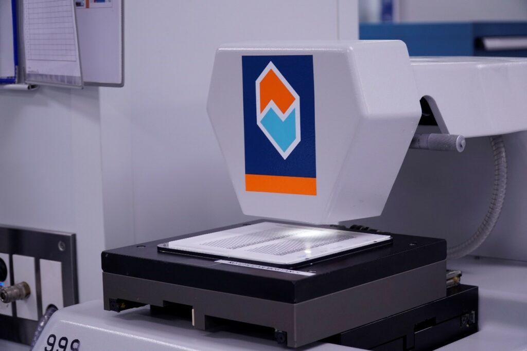
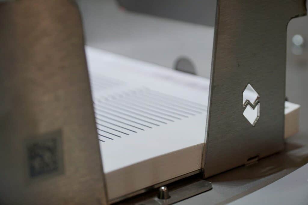
Depending on the sensor, the sheets outlined in the design are stacked in order, according to their function in the sensor. Everything is controlled by a bar code system.
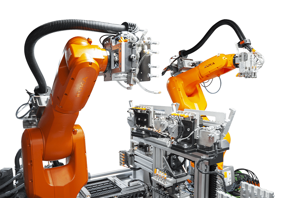
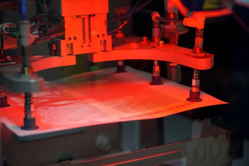
In order to stack the sheets, the transporter PET that has accompanied the ceramic substrate during the entire process must first be removed. The different sheets are layered on top of each other and centred using the fiducial markers, which are controlled by the artificial vision cameras, to create a substrate with all the necessary layers. This houses between 60 and 90 sensors. The stacking is done by a robot arm to optimise the work.
The stacking is carried out by a robot arm that optimizes the work
11. LAMINATING
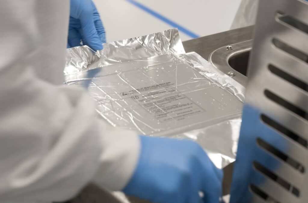
The substrate, which is made up of 10 layered sheets, is still a soft, malleable material and the layers are only provisionally bound.
The FAE isostatic laminator uses water at a temperature of 70°C to apply a constant, homogeneous pressure of 300 bar to the sheets for 30 minutes in order to completely bind the sheets together.
12. PROTECTION
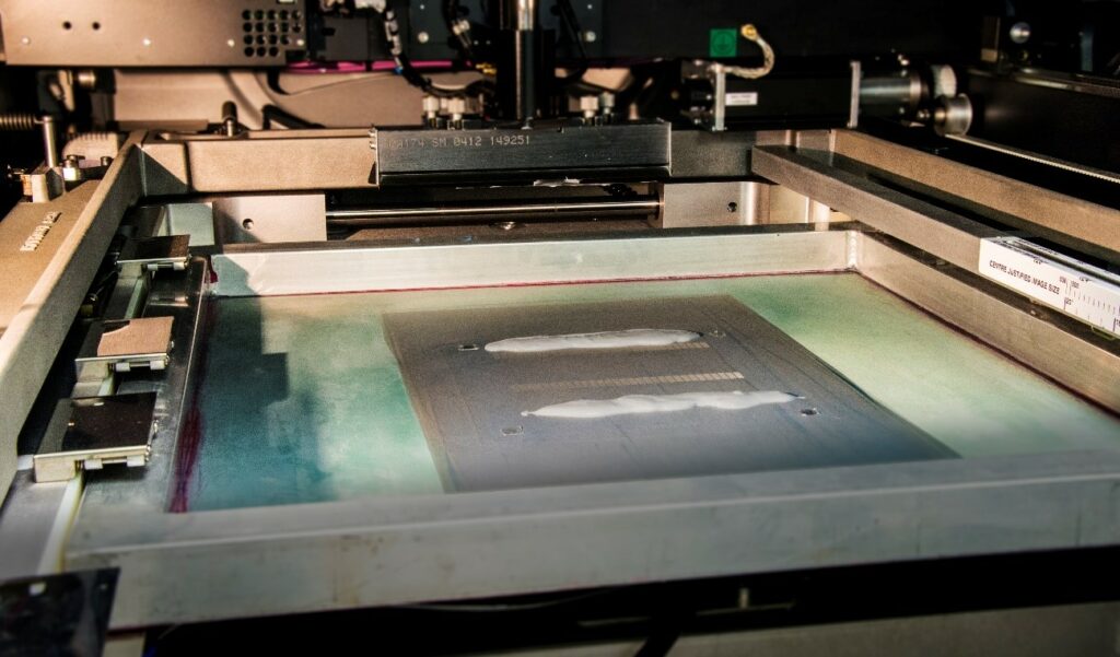
Using another screen FAE printing machine, a resistant layer is applied. This protects the electrodes and the parts of the sensor that will be exposed to the exhaust gases, in this way lengthening the lifespan of the sensor.
13. PERSONALISING
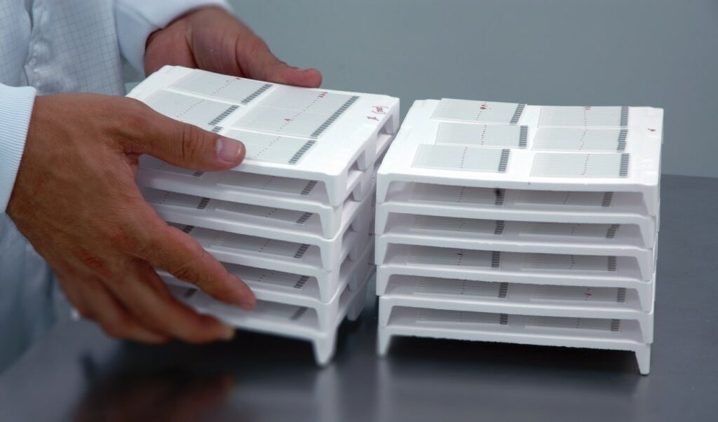
Prior to the sintering of the ceramic, and while the substrate is still flexible, the sensors are pre-cut into units of 10. This helps to facilitate their subsequent handling and the verification of their functionality.

14. SINTERING
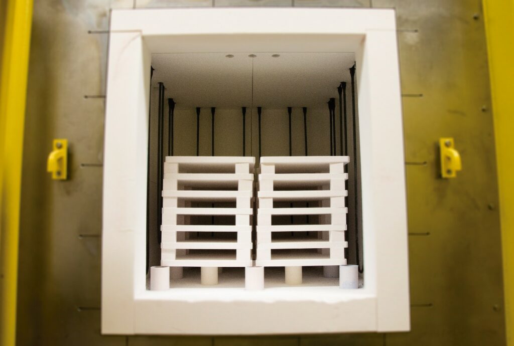
The pre-cut FAE sensors are placed in an oven where they will reach a temperature of up to 1500°C for 2-3 hours, using a special temperature control system. During the sintering process, the molecules of organic materials in the ceramics and the solvents in the inks evaporate, and the materials harden.
15. VERIFICATION
Each group of 10 pre-cut sensors is subjected to a check on the sensor and the resistance of its heater. The FAE sensors are brought to high operating temperatures and their strength and functionality are checked.
The FAE sensors are now cut one by one, and are ready to be assembled into their sensor group, and then placed into the oxygen sensor of whichever car they’re intended for.
The sensor element is the heart of the lambda probe and, for this reason, its manufacture in such a controlled environment is so important.
FAE is one of the few manufacturers in the after-sales market with this type of facility, which is why it is a Key Partner for this product.
